China Mobile carried out a large-scale deployment of time networks in the 4G era. The time network and the PTN/IPRAN mobile backhaul network are physically one network. The main problems are the complexity of clock network planning, low configuration efficiency, and lack of an effective fault isolation scheme for large-scale networking. The clock fault in one area may affect the clock service in another unrelated area, so it is difficult to locate the fault. The integrated intelligent time network solution has been developed to address the issue of large-scale deployment. The solution breaks the restriction that the time network and the service network need to share the same network in the 4G era. The core idea is to deploy a single-fiber bidirectional private time network on the core aggregation ring and use base stations to backhaul GNSS signals at the access network. The time network is divided into the domains that are managed and controlled by big data or AI technologies.
Key Technologies
The intelligent time network uses an intelligent management and control system to implement hierarchical fault isolation and intelligent fault analysis, which can solve the deployment and location problems of large-scale time networks.
Time Network Division
The networking algorithm of the time network is dynamically generated in real time by the best master clock (BMC) algorithm with adaptive meshing.
The undivided time rings synchronize the time according to the configured master/slave time priorities, and the time rings of all devices are interlinked. When an access ring device fails, for example, when its priority is changed to the highest or higher priority, the time of the lower-priority device in the local access ring, other access ring or the aggregation core ring will follow the time of the faulty device. The fault affects widely, and it is easy to cause repeated network oscillation, so it is difficult to locate the fault.
To accelerate the fault location and restrict the impacted scope, the network can be divided into areas by levels. The time source can be moved down to the place where the aggregation and core networks meet to implement multi-source multi-area division physically, or the network can also be divided logically, with some transport nodes abstracted into virtual time source injection points (Fig. 1).
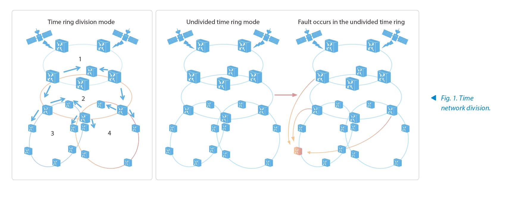
According to the network layer where the nodes are located, the network management controller divides the time network into core aggregation, common aggregation, and access ring time rings. Unidirectional timing between different layers is implemented in the following direction: core aggregation → common aggregation → access ring. The ring at a lower layer cannot provide time to a higher-level ring, which can isolate faults between access rings. The fault and impacted scope at each layer are clear, which makes it easy to use the BMC algorithm manually to isolate faulty areas quickly.
Automatic Planning
Automatic planning refers to automatically calculating and planning active and standby clock synchronization topologies of all or specified NEs in accordance with the physical topology and NE clock synchronization attributes, solving clock time configuration according to the rules and eliminating the difference between new and old devices to implement automatic port selection. For example, a single-fiber bidirectional path is preferred for network construction.
When the network changes, the changed network area is automatically synchronized and reconfigured according to the changed topology to achieve the minimum change, and the existing synchronization configuration in other areas is not affected. The automatic planning of the time network is efficient, simple and easy to configure, which reduces the complexity and human errors of network planning.
Single-Fiber Bidirectional Time Transfer
Above the aggregation ring of the transport network, the long-haul, OTN and packet devices may coexist, and their time precision directly affects that of the downstream access ring. Dedicated links and GE/10GE single-fiber bidirectional optical modules are used to form the special clock time ring above the aggregation layer. It can not only reduce the latency deviation caused by fiber asymmetry, but also avoid the uncertain errors caused by coherent optical modules. This ensures the interconnection between OTN and packet devices while enhancing its stability.
After the single-fiber bidirectional transport is introduced, the latency difference caused by long-haul transmission of different wavelengths in the optical fiber should also be considered. Take the GE 40 km optical module solution as an example. The wavelength range of lasers defined by the IEEE standard is 1310 to 1490 nm, and the dispersion coefficients in 1310 nm and 1490 nm windows are different. If G.652 optical fibers are used and the corresponding transport latency difference is +/–1.28 ns/km, the 40 km transmission will result in a time difference of +/–25.6 ns. Therefore, when single-fiber bidirectional optical modules are used for networking, if there is no compensation, the time error caused by the accumulated wavelengths in the existing network cannot be ignored under the improper matching relationship.
Because the relationship between wavelength and latency is linear, the latency deviation can be calculated by automatically estimating the latency when the wavelength is known, so as to offset the error caused by the wavelength deviation.
The management and control equipment automatically select a single-fiber bidirectional path according to the existing network equipment.
Base Station Time Backhauled to Transport Network
Wireless base stations use GNSS and 1588V2 for time synchronization at the air interfaces. To ensure stable and reliable synchronization, the base stations often activate the two technologies at the same time to protect each other. The system backhauls the difference between the time obtained by GNSS and by 1588 to the transport equipment at the access layer and reports it to the transport network management and control system. The controller can analyze the data of upstream and downstream sites to infer the performance of base stations or the transport network and further locate the root cause of the fault.
The comparison information between the satellite and transport equipment backhauled by the base station provides the absolute time difference between the base station and the ground. The transport access equipment can calculate the reliability of the current equipment time according to the information obtained from multiple base stations and upstream and downstream nodes. The comparison information can also be combined with other clock time alarms as well as configuration and performance data to form important feature data of intelligent fault diagnosis, which is used to calculate device status in the network without access to GNSS.
Intelligent Fault Diagnosis of Clock Time
The intelligent fault diagnosis of clock time includes fault identification, fault location and root cause determination. The basic idea is that the network management controller uses clock time-related configuration, alarm and performance data to carry out big data analysis and intelligent fault diagnosis.
Fault Identification
Fault identification of the clock time network is to identify whether the clock time network is faulty using the knowledge graph or AI technology based on the collected topology structure of the clock time network and the configuration, alarms, and performance feature data of clock time at each NE node.
AI fault analysis is an application of machine learning in communication networks, which is suitable for fault analysis with less fuzziness in complicated networks. Using the AI technology to identify the faults of a clock time network involves three steps. First, collect the marked sample data of the clock time network and convert it into a train set. Second, establish the corresponding AI model. Finally, train the model using the train sample set, so that the model has the capability of identifying clock time network faults.
ZTE has two technical solutions for fault location: fault location based on the fault dependency graph and rules, and fault location based on the graph neural network.
—Fault location based on the fault dependency graph and rules: This solution needs to establish the fault dependency graph based on the existing clock time configuration and actual clock and time paths. To locate a fault, the system searches for the faulty entity node based on the established fault dependency graph and the node judgement rules. In general, the faulty entity node at the bottom layer of the dependency is the location of the fault to be determined.
—Fault location based on the graph neural network: The graph neural network is a machine learning connection model. It captures the dependency of the graph through the message transfer between the nodes of the graph, and extends the deep neural network from dealing with traditional unstructured data to higher-level structured data. The fault location based on the graph neural network uses not only the feature data of its own nodes, but also the feature data of adjacent nodes. In this way, more fault feature data is collected, and the accuracy of fault location is higher. The implementation of fault location based on the graph neural network involves four steps. First, define fault location scenarios abstractly, and transform the fault location issue into the node classification issue based on the graph neural network. Second, set up an end-to-end node classification model based on the graph neural network needs. Third, collect the marked sample data of the clock time network and convert it into a train sample set. Finally, train the established fault location model based on the graph neural network, so that it has the capability of locating the faults.
Conclusion
With rich experience in large-scale deployment of PTN time networks in the 4G era, ZTE's intelligent time network solution has been gradually trialed in existing networks of Jiangsu Mobile, Fujian Mobile and Beijing Mobile, and has been significantly improved in iteration. The solution has addressed the issues of large-scale time network deployment and troubleshooting in the 4G era, paving the way for constructing a 5G transport time network.