Adaptive Functional Splits Enable Brand-New 5G RAN Architecture
Release Date:2017-01-06
By Xu Fang
Click:
5G is more and more close to people’s life. With the arrival of 5G, many new business opportunities will be created such as driverless car, massive sensors, high quality video, and virtual reality. How to introduce 5G into today’s 4G networks and to satisfy the diverse requirements have become a major concern of the new network architecture. This article will focus on 4G evolution and 5G RAN architecture.
With the 4G evolution well under way and the 5G being introduced at a fast pace, RAN architecture is undergoing a transformation. The RAN architecture needs to increase deployment flexibility and network dynamicity so that operator networks can meet increasing performance requirements while reducing costs. In the 3G and 4G stage, RAN consists of base band units (BBUs) and remote radio units (RRUs), and can be gradually transformed to Cloud RAN—a redefinition of the BBU-RRU architecture that determines where to place anchor points to enhance the network needing combined operations and identifies the latency-critical functions that need to be placed near the antenna elements. Cloud RAN can adapt to user scenarios such as ultra-low latency and ultra-high throughput and also to different transmission environments such as ideal fronthaul (FH) or non-ideal FH. Adaptive software-defined split architecture will be deployed for general-purpose and special hardware, with functions ideally placed to maximize scalability as well as spectrum and energy efficiency.
Therefore, how to split the RAN functions has become the focus of attention. The RAN functions will be split in two steps: first determine functional splits and then split the functions dynamically and appropriately.
Functional Splits
In the study item for a new radio access technology, 3GPP is expected to study different functional splits between different functional split options. In the legacy RAN, FH refers to the interface between BBU and RRU, which is called common public radio interface (CPRI), as shown in the Option 8 in Fig. 1. However, in the new RAN, user data rates are high and the throughput transmitted in FH is very huge, while the latency requirements of CPRI are still very strict, so the transmission condition of FH will be more critical. If an operator has ideal FH, the Option 8 will be suitable for existing C-RAN architecture. But if the operator has non-ideal FH, new options must be figured out for functional splits between central and distributed units.
If the same radio protocol stack as used in LTE will be used, then there could be the following options for functional splits between central and distributed units, as shown in Fig. 1. The signaling overhead, resource pool sharing, CAPEX and OPEX for RRU as well as strict latency requirement for HARQ response shall be considered, and the fronthaul interface shall not be made quite complex. Therefore, it is recommended that the legacy Option 8 be remained for ideal FH, and Option 1 and Option 2 for the non-ideal FH. In this way, a flexible split of RAN functions can be provided for different scenarios.
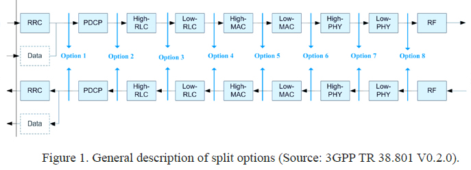
Option 1: RRC is in the central unit. PDCP, RLC, MAC, physical layer and RF are in the distributed unit. In this case, signaling can be coordinated smoothly, and applications can choose to be offloaded to a mobile edge application running on a mobile edge host.
Option 2: RRC and PDCP are in the central unit. RLC, MAC, physical layer and RF are in the distributed unit. This can reduce latency requirement by an HARQ process in a remote node.
Option 8: RF functionality is in the distributed unit and upper layers are in the central unit. This is the traditional BBU-RRU split that has been used in the C-RAN architecture in ideal FH.
Implementations and Deployments
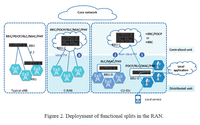
Let’s see the whole topology of how these functions are deployed in the split RAN architecture. On the left side of Fig. 2 is a typical eNodeB protocol stack topology that is now used by LTE. The protocol stack topology can support normal services with ease. In the middle of Fig.2 is a classical solution in the context of C-RAN within the CPRI. The solution is used in Option 8. The A/D conversion is performed in RRU, while other functions are centrally processed. Option 1 and Option 2 are on the right side of Fig. 2. If fibre fronthaul is not available, low latency connectivity between centralized processing and RRU cannot be guaranteed. Therefore, an option is needed to split the functions that are closely tied to and synchronous with the radio such as PHY, MAC and RLC related functions, and the functions that are less tightly tied to and in LTE asynchronous with the radio such as PDCP and RRC functions.
Now let’s see how different scenarios work on this architecture.
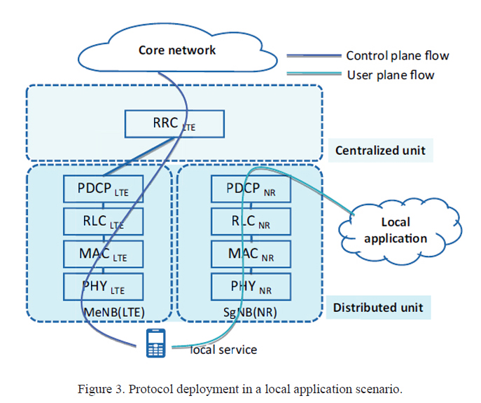
Option 1 (e.g. mobile edge clouds)
The functional split in this option is similar as 1A architecture in dual connectivity. In this scenario, 5G user plane has complete and separate process and can be used in mobile edge services with tight latency or be used to meet local content caching requirements (Fig. 3).
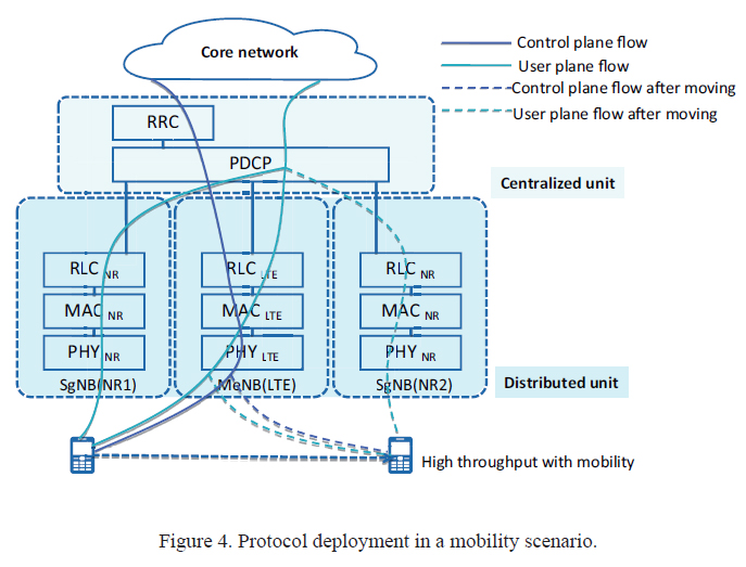
Option 2 (e.g. high throughput with mobility)
The functional split in this option is similar as 3C architecture in dual connectivity. In this scenario, SgNB (NR) mobility is hidden to core network, so the requirements for NR mobility such as watching the video in a high-speed vehicle can be relaxed (Fig. 4).
Option 8 (e.g. C-RAN)
If fiber fronthaul is available and a high degree of centralization is desired, the legacy solution with current C-RAN architecture can be used.
Besides these alternatives, ZTE’s proposal for split RAN architecture also supports the flexibility to move functions as required by services. New use cases and transmission conditions are flexibly supported. As an evolution of 4G RAN, the split architecture can be gradually introduced with new business models, new services and new products.
relative articles