Leading Innovation in Microwave Broadband Transmission for Pre5G/5G
Release Date:2017-11-16
By Yao Wei, Li Changxing
Click:
With the continued evolution of Pre5G/5G applications in the telecom market, mobile backhaul has posed increasingly higher requirements on transmission capacity and delay of microwave devices. It is therefore necessary to constantly innovate and enhance the technologies to increase transmission throughput and reduce the delay.
High-Order Modulation and High Bandwidth
The most direct way to improve transmission bandwidth is higher-order modulation. The improvement in modulation from 1K QAM to 2K QAM and 4K QAM can lead to the increase of bandwidth by about 10% and 9% respectively. At present, the mainstream modulation in the industry is 4096 QAM. It is expected that the highest modulation will increase by one order every one to two years. With the hybrid automatic repeat request (HARQ) technology, microwave equipment should be able to support 8192 QAM and even 16384 QAM. Another consideration is to expand the spectrum bandwidth from 56 MHz to 112 MHz, which increases transmission capacity by 100%. Conventional microwave spectrum resources are limited and cannot be expanded freely. E-band has rich spectrum resource and can support a maximum of 2 GHz bandwidth, in which a wider frequency band uses relatively lower-order modulation. For example, 256 QAM can achieve a transmission bandwidth of 10 Gbps. E-band is one of the optimal routes to wireless x-haul and will play a more important role in future 5G transmission applications due to its high capacity and low delay. The study of higher frequency bands such as W-band (92–114.5 GHz) and D-band (130–174.7 GHz) is underway in the industry, which can provide higher spectrum bandwidth.
Spatial Multiplexing
In addition to enhancing modulation and expanding spectrum bandwidth, spatial multiplexing can also be used for improving channel capacity. Co-channel dual-polarization (CCDP) is commonly used to provide twice the transmission capacity of single polarization. Also, 2×2 line of sight multiple input multiple output (LOS MIMO) can be used to achieve twice the transmission capacity of single polarization. Therefore, the combination of CCDP and 2×2 LOS MIMO can enable four times the transmission capacity of single polarization. In the future, LOS MIMO can extend to a higher level, for example, 4×4 LOS MIMO and N×N LOS MIMO.
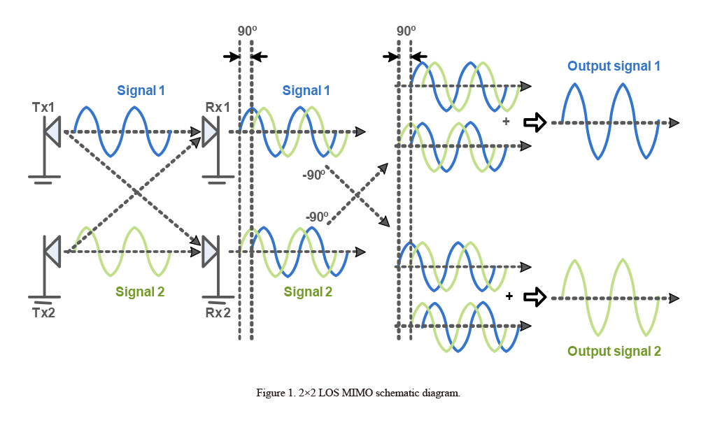
Take 2×2 LOS MIMO as an example (Fig. 1), the spacing of antenna arrays should meet certain requirements, depending on the one-hop link distance and operating frequency. At the receiver end, any Rx can receive a primary signal and a cross signal. For the cross signal, there is a path distance difference (Δ) on the propagation path, which finally shows up as a 90° of phase delay in the cross path. During the baseband processing, as the receiver changes its mode from single-channel receiving to dual-channel receiving, the baseband algorithm must support more efficient phase noise suppression to ensure that MIMO antennas can stably operate in the high-order modulation and high-bandwidth mode. In actual applications, the issues concerning power imbalance between channels, asymmetric antenna spacing, and pole tilt need to be considered and coordinated in the system in terms of RF circuit and baseband processing.
To meet the strict requirements of microwave LOS MIMO for the spacing of antenna arrays, two solutions will be used in the future for easy deployment. One solution is closed-loop LOS MIMO, in which the phase difference between signals received from two channels is estimated at the receiver end, and then the phase is compensated, so that the two signals are orthogonal to each other. The other solution is phased array antenna-based LOS MIMO, where the phased array antenna consists of a set of independent antenna array elements whose relative amplitude and phase relationship are regulated by control circuits. The orthogonality of LOS MIMO is controlled by control circuits of the phased array antennas rather than relying on the path delay of space links.
As the planar phased array antenna technology develops, innovations in an antenna system have gradually applied for microwave devices. For a high-frequency band system (E-band), digital beam forming (DBF) can be used to achieve uniplanar antennas while allowing for multi-beam forming. The DBF technology similar to massive MIMO will enable a perfect combination of high bandwidth and high spectrum utilization, making it possible for a microwave communication system to dramatically increase its capacity in the Pre5G/5G era.
Innovation on the Service Side
Facing the challenges of low delay and high bandwidth put by 5G networks, ZTE has put forward its MultiBand-based solution that can use efficient PLA and flow control technologies to intelligently divide traffic flow by service priority. The solution can also balance the transmission capacity and service priority by binding wireless channels of conventional and E-band microwave devices. For the changing channel conditions, ACMB and QoS technologies can be combined to achieve lossless switching and transmission of high-value traffic flow.
From the perspective of baseband service processing, the high-capacity low-latency compression algorithm based on Ethernet packets has been widely applied in fronthaul, backhaul and hybrid haul scenarios. As new demands for MPLS and eCPRI emerge, the corresponding efficient service compression technologies are also evolving.
Innovative Techniques
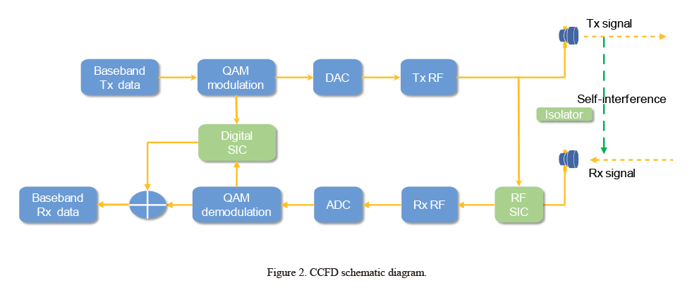
Co-time co-frequency full duplex (CCFD) is a kind of technique that can improve spectral efficiency. Compared with traditional microwave transmission, CCFD saves half of spectrum resources because it can achieve full duplex by occupying only a single frequency point. However, CCFD can lead to co-channel interference also called self-interference (SI) between the Rx and Tx. Therefore, the key to CCFD lies in self-interference cancellation (SIC). At present, there are three types of SIC: antenna isolation, analog-domain SIC (RF SIC), and digital-domain SIC. In the antenna isolation mode, Rx and Tx antennas are separate from each other at a certain distance by an in-between isolator. In the digital-domain SIC mode, the transmitted digital signals are sent to the Rx baseband module where SI signals are eliminated through a specific algorithm (Fig. 2).
The orbital angular momentum (OAM) modulation technique uses OAM modes carried by carriers as modulation parameters and also uses inherent orthogonality of the OAM modes to modulate multiple signals onto different OAM modes, which provides a new degree of freedom. The basic principle is as follows: A rotation factor related to the spatial phase angle is added to a normal electromagnetic wave, and then the normal electromagnetic wave is converted to a vortex electromagnetic wave. Vortex electromagnetic waves in different modes have different eigenvalues, and they are orthogonal to each other. This feature allows multiple vortex electromagnetic waves to be transmitted in parallel on the same frequency point. In theory, the vortex electromagnetic waves with different eigenvalues do not interfere with each other. The challenges of OAM lie in how to generate vortex electromagnetic waves that have different eigenvalues, how to isolate the vortex electromagnetic waves with different eigenvalues at the Rx end, and how to compensate channel distortion when orthogonality of the electromagnetic waves is impaired during the transmission in the atmosphere.
Conclusion
This paper gives a technical illustration of future microwave transmission evolution. Although some techniques are not yet mature, they have become hot topics of research in the industry. Some of them have made significant achievements in the lab. As innovative techniques continue to evolve, microwave devices will be poised to meet the challenges of large capacity and low delay in the Pre5G/5G era.
relative articles