A New Two-Branch Amplification Architecture and its Application with Various Modulated Signals
1 Introduction
The design of new wireless transmitters is becoming more complex as demand on spectral resources increases and available power for wireless terminals becomes limited. The amount of band occupied by the modulation scheme must be as small as possible in order to accommodate many channels in a given band. For this reason, complex modulation schemes such as M-ary quadrature amplitude modulation (M-QAM) (M up to 256) and M-ary phase shift keying (M-PSK) modulation have been proposed [1], [2]. These modulations are spectrally efficient, especially with baseband filtering such as root raised cosine filtering (RRCF). However, the resulting filtered signals have very high peaks, which are problematic for the power amplifier (PA) stage. To achieve linear amplification with acceptable power efficiency, many approaches have been proposed [3]-[10]. In one approach, single branch amplification, typically a class-AB or class-B amplifier, is used to reduce power consumption. A linearization stage, such as digital predistortion [3]-[5], is generally needed with such topology to achieve good linearity and meet linearity requirements. Another approach is to use multibranch schemes [6]-[10], which are more complex but offer greater flexibility. The feed-forward technique [6] is very linear, especially for large-bandwidth signaling, but is not power efficient. Linear amplification with nonlinear components (LINC) [7]-[10], based on outphasing, is another solution. LINC is inefficient in terms of high crest factor signals, which measure the ratio of peak to average power.
Modulations with constant amplitude, such as continuous phase modulation (CPM) [2], [11]-[14] have also been developed. The information is carried in the signal’s phase, which is shaped with different types of windows for smooth phase transitions. These modulations have constant amplitude, and efficient non-linear amplifiers can be used, which makes CPM attractive. However, the spectral efficiency of this modulation depends on signal characteristics such as phase shaping and modulation index [2], [11] and is generally quantized in terms of out-of-band radiation, that is, at the side-lobe level. Unfortunately, spectrally efficient CPM signals, particularly those with low modulation index, have degraded bit error rate (BER) performance and require complex receiver architecture [2], [11]. Pulse-shaping CPM signals can therefore be considered. However, the constant envelope property is lost, and the design of a linear, power-efficient transmitter arises as a new issue.
In this paper, we propose a new two-branch amplification architecture that combines digital signal processing and RF front-end optimization. In section 2, we give a detailed description of the transmitter and the motivations for using a two-branch structure. The signal decomposition technique and overall power efficiency are also presented. In section 3, we investigate the use of this system with digitally modulated signals such as M-QAM and filtered CPM. In section 4, we discuss the performance of the proposed architecture and compare it with a single-ended class-B PA. Concluding remarks are given in section 5.
2 Proposed Two-Branch Amplification System
Using a baseband-shaping filter for digital modulations is unavoidable because it limits the amount of band occupied by the transmitted signal and eliminates inter-symbol interference (ISI) according to the Nyquist criteria [2]. However, baseband-shaping filters increase the signal crest factor, which directly impacts efficiency in the amplification stage. For example, a quadrature phase-shift keying (QPSK) signal has a constant amplitude. When filtered with an RRCF filter that has a roll-off (αrc) of 0.2, the crest factor of the signal can rise up to 5 dB. For a 16QAM signal, the crest factor increases from 2.5 dB for a non-filtered constellation to around 7 dB with the same RRCF (Table 1).

In both cases, the amount of spectrum occupied by the transmitted signal is greatly reduced by filtering. But this comes at expense of a dramatic increase in envelope variation. Using single-ended amplifiers generally requires high back-off levels in order to maintain acceptable linearity, and these high back-off levels reduce power efficiency. Therefore, to improve efficiency while ensuring good linearity, we propose a new two-branch amplification system. This system is based on a special decomposition of the filtered input signal. First, the decomposition is applied in baseband, and then specifications of the RF front-end are determined. This entails specifying the output combining structure and power handling capabilities (P1dB and gain) of the amplifiers that are needed in each branch. Therefore, the amplifiers and output combiner must be designed specifically to meet the established specifications.
2.1 Signal Decomposition
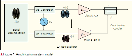
The filtered output of a digitally modulated signal is denoted by h (t ). It is decomposed in baseband into two different signals, m (t ) and r (t ), which have desired power properties and are amplified by optimized amplifiers. m (t ) is the main signal, has a constant or low-varying envelope, and carries the main part of the information. r (t ) is the remaining part of h (t ). Geometrically, this can be represented as a projection of the vector h (t ) on the chosen region for m (t ) followed by a calculation of r (t ). The placement of the projection region is denoted by γ, the ratio of average power of m (t ) to average power of r (t ). γ impacts the power levels in both branches and the ratio between these power levels. This ratio, in turn, determines the characteristics and performance of the required amplifiers. The optimal choice of γ is a function of the probability density function (PDF) distribution of h (t ) and should be such that the difference between the average powers in both paths is minimal.
2.2 RF Front-End Architecture
The decomposed signal must be amplified and combined using the RF transmitter front-end depicted in Fig 1. The RF transmitter front-end consists of two PAs (main and auxiliary amplifiers) and a directional coupler. The main amplifier generates a high-power output signal and should be a highly efficient class-B, C or F amplifier [15]-[17]. Because the input signal has a low-varying envelope, a non-linear power-efficient amplifier can be used without introducing significant distortion into the main signal component. The auxiliary amplifier amplifies the low-power residual signal. This amplifier must be sufficiently linear to keep the overall system linear. Then, a directional coupler is used to sum the outputs of both amplifiers and generate an amplified version of the filtered signal. A directional coupler is a four-port device typically realized in microstrip or stripline technology by closely spaced transmission lines [6].
The parameters of this architecture are as follows:
Input parameters
m (t ) input signal of the main amplifier
r (t ) input signal of the auxiliary amplifier
P in_main average power of the main signal
P in_aux average power of the residual signal
γ ratio of the average power of the main
signal to the average power of the
residual signal
Δm (t ) crest factor of the main signal
Δr (t ) crest factor of the residual signal
Amplification stage parameters
α insertion loss of the coupler
β power coupling coefficient
g main main amplifier’s gain
g aux auxiliary amplifier’s gain
P DC_main DC power of main amplifier
P DC_aux DC power of auxiliary amplifier
η main main amplifier power efficiency
η aux auxiliary amplifier power efficiency
Pout_main average output power of the main
amplifier
Pout_aux average output power of the auxiliary
amplifier
P1 dB(A main) P1dB of the main amplifier
P1dB(A res) P1dB of the auxiliary amplifier
The input parameters for the amplification stage are obtained after optimization has been done in the signal decomposition stage. The amplification stage parameters are the parameters for both amplifiers and the directional coupler. Based on the architecture in Fig. 1, we can write the following equations:

The total output power of the amplification system, Pout, is given by:

The coupler’s parameters satisfy the following equation [6]:

For perfect linearity, the two paths must be balanced and must have the same gain. This condition can be mathematically expressed as

With the system parameters established, it is possible to determine the ratio P1dB (A main) to P1dB (A res) and the global power efficiency of the proposed amplification architecture. After mathematical simplification (Appendix A), the final expression of the ratio P1dB (A main) to P1dB (A res), denoted as χ , is

Based on χ, it is possible to predict the potential use of this technique with a given signal. As shown in (7), this parameter depends only on the signal envelope statistics and the coupler parameters. The global efficiency is expressed as

The power efficiency of the amplification system is then a function of the power efficiency of the two amplifiers, the coupler parameters, and the ratio of the average powers of both signals. For a given set of amplifiers, fixed η main and η aux, and a given signal, fixed γ, the optimal efficiency depends solely on the choice of the coupler. A very low coupling coefficient leads to a highly inefficient auxiliary PA. Too much coupling leads to considerable loss in the main path.
In the next section, we discuss the use of this amplification technique with different input signals. Based on χ, it is possible to determine whether the system will be power efficient with a given signal or not.
3 Use of The Proposed Amplifier with Various Signals
3.1 The Case of M-QAM Signals
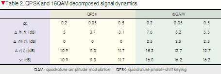
The first step in determining the suitability of this technique for the signals of interest is to decompose the signals and calculate all obtained parameters, particularly γ, Δm (t ), and Δm (t ). Then, χ for different coupling coefficients is calculated, which allows us to determine whether there is a potential gain when using this technique. For M-QAM signals, we focus on the QPSK and 16QAM modulations. For the QPSK, the main signal corresponds to its mean value m (t ). r (t ) is the vectorial difference between m (t ) and h (t ). For the 16QAM signal, we project h (t ) onto the region centered by its mean value and reduce the crest factor of m (t ) to around 2.5 dB, the crest factor of the non-filtered 16QAM signal. Again, r (t ) is the vectorial difference between m (t ) and h (t ). This operation is performed for different α rc. The statistics for each signal component are given in Table 2. The crest factor of r (t ) is very high, and this increases the power requirements on the residual amplifier, particularly in QPSK modulation.
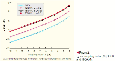
χ can be plotted using these component statistics for varying coupling factors, and Fig. 2 confirms the above observations. Depending on the constellation and the value of α rc , a high χ is obtained for a coupling factor order of -3 dB or less. This implies that around half the power generated by the main amplifier is used to compensate for the coupler loss. The high crest factor of r (t ) imposes a high P1dB on the auxiliary amplifier, in the order of the main amplifier. This technique, accordingly, is not power efficient with such signals.
3.2 CPM Modulation: The Impact of Filtering CPM Modulations on Spectral Efficiency and BER
CPM modulation is a class of phase modulation that has been widely used in wireless communication systems such as GSM [13], [14]. The expression of the CPM signal is

where fc is the carrier frequency, φ 0 is the initial phase, E is the symbol energy, T is the symbol duration, and φ (t,I ) is the time-varying phase of the carrier. The time-varying is defined as

where θn is the accumulation of all symbols up to time (n-1)T, h is the modulation index, and q (t ) is the integration of some pulse g (τ), that is,

The modulation order M, the value of h, and the pulse type directly impact the spectral characteristics of the resulting signal and its detection performance [11]. Small values of h result in CPM signals that occupy a small amount of bandwidth but have poor detection. Compared to rectangular pulses, smoother pulses, such as Gaussian pulses, improve spectral efficiency at the expense of receiver detection. In this paper, we consider binary CPM where h is 0.5. When g (τ ) is rectangular, the corresponding modulation is called minimum shift keying (MSK). When g (τ ) is Gaussian, the obtained signal corresponds to the Gaussian MSK (GMSK) modulation, which has a more compact spectrum with good error detection.
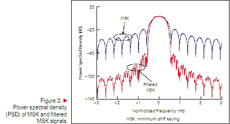
Both signals have constant amplitude according. This enables the use of highly efficient amplifiers such as class-C or F and makes this type of modulation very attractive. However, the amount of bandwidth occupied is relatively high in terms of fractional out-of-band radiation (Fig. 3). To reduce the amount of bandwidth occupied, we introduce RRC filtering with αrc set to 0.35. For both signals, the side lobes are dramatically attenuated, increasing spectral efficiency (Fig. 3). The resulting change in signal dynamic, expressed in terms of crest factor, is relatively small:
Δh (t ) = 0.62 for MSK and Δh (t ) = 0.77 for GMSK. The phase transitions in time are too small. Thus, when these signals are filtered, the output signal trajectories stay close to the unity circle, resulting in a small added amplitude modulation. A finite peak-to-peak variation is obtained and does not exceed 2.1 dB.
One issue with the filtered CPM modulations is the impact of RRC filtering on system-level performance. To study this impact, we constructed a complete MATLAB/Simulink model of a wireless link using filtered modulation over an additive white Gaussian noise (AWGN) channel. On the receiver side, we used a matched RRC filter combined with coherent demodulators available in the Simulink library. There is no differential pre-coding, and we use a coherent direct demodulator with maximum likelihood detector. We conducted several simulations of the constructed model to evaluate BER vs. Eb /N0 of the filtered MSK/GMSK signal over an AWGN channel. The results of these simulations with GMSK modulation are shown in Fig. 4.
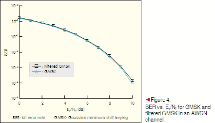
There is no significant degradation because a matched RRCF filter is used at the receiver side. ISI is then largely reduced, and the signal is correctly demodulated. Similar results are obtained with the MSK signal. Given the better occupation of spectrum, good BER, and low signal dynamic, the filtered MSK-based modulated signal is worth considering.
3.3 Application of the Proposed Amplifier to the Filtered CPM Modulation
To determine the performance of the proposed amplification architecture, we use the MATALB/Simulink model previously developed and add a baseband model for the RF front-end. We decompose the filtered MSK-based signals. Table 3 shows the dynamics for the residual signal as well as the difference in average power between both branches.

The very high γ can be explained by the level of side lobes for each modulation. As a result, the overall efficiency is expected to be higher in this case. Although the crest factor of the residual signals is considerably high, it is much lower than in QPSK. χ is then plotted against the coupling factor for both considered signals (Fig. 5). For a coupling level of -8 dB, χ is around 15 for GMSK and around 10 dB for MSK. In comparison purpose, for the same coupling level with QPSK signal, χ was -7. This implies that this architecture is perfectly suitable for this type of signals. In the next section, we study the power efficiency of the system fed with these signals.

4 Architecture Performance with Filtered CPM Signals
In this section, we consider the amplification of filtered MSK-based signals and its impact on transmitter power efficiency and linearity. We have considered several amplifiers for the residual signal r (t ), each corresponding to an amplification class. The main amplifier is assumed to be a 100% efficient class-C or class-F amplifier. For each secondary amplifier, we compute power efficiency, optimal coupler coefficients, overall efficiency, and the system linearity.
4.1 Single Branch Class-B Amplification
The first intuitive amplification architecture proposed is a single-branch system. Because the input signal has a varying envelope, a class-C amplifier with low conduction angle and high power efficiency causes clipping and is therefore inappropriate. By contrast, a class-B amplifier has a conduction angle of 180°, allowing the entire signal to be amplified. Such an amplifier can be used for the filtered MSK signal. In this paper, we consider a realistic class-B amplifier designed with MRF9060—a 900 MHz Freescale laterally diffused metal oxide semiconductor (LDMOS) transistor.
Fig. 6 shows the simulated output power and efficiency of the class-B amplifier versus input power.
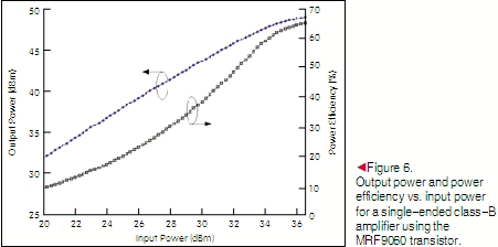
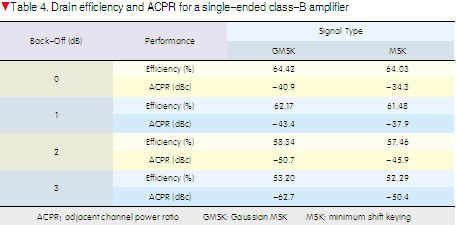
This PA has a peak output power of 49 dBm and DC-RF efficiency of 65%. A model of this amplifier is implemented in Simulink for the three MSK filtered signals. For each signal, we compute the average power efficiency, and linearity expressed in terms of adjacent channel power ratio (ACPR) for different back-off levels. The results of these simulations are summarized in Table 4. When the PA is operated at its saturation point, it is highly efficient but has poor linearity. Higher efficiency is obtained for GMSK because the PAR is lower than in MSK. As the input back-off is increased, linearity is improved at the cost of power efficiency. Very low ACPR is obtained at a back-off level of 3 dB. These results give a realistic idea of the performance that can be expected from a single-ended PA and will be used as a reference for a subsequent comparison with the proposed two-branch amplification system.
4.2 Amplification of the Residual Signal: Class-AB
Class-AB is an intermediate class between classes A and B. It has better linearity than class-B but lower efficiency. We use a measurements-based model of a 45 W peak Motorola MRF21045 base station amplifier [18]. The amplifier’s DC-RF conversion efficiency and power gain are shown in Fig. 7.
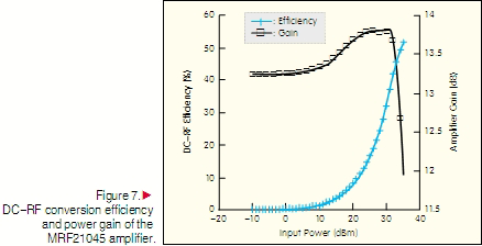
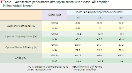
Gain varies rapidly around the point of maximum efficiency, and this affects the linearity of the system. Therefore, when assessing the system’s efficiency, linearity also needs to be considered. We use three input power levels (30 dBm, 32 dBm, and 35 dBm) and compute the average efficiency of the class-AB amplifier, assuming that the main amplifier is 100% efficient. We then evaluate the overall efficiency for each signal as a function of the coupling factor β. For a given γ and η aux (8), optimizing the overall efficiency is equivalent to optimizing the coupler coefficients. For both signals, we calculate the auxiliary amplifier efficiency, the optimal coupler, and the corresponding optimal overall efficiency. To evaluate linearity, we calculate the resulting ACPR. Table 5 summarizes the optimal configuration performance and gives the output signal linearity expressed as ACPR.
For both signals, we have comparable second amplifier efficiency. However, because GMSK has a higher γ, it also has a higher overall efficiency. Efficiency can reach around 87% when the class-AB amplifier is in deep saturation. Overall efficiency of 79.5% can be achieved with the MSK signal. In terms of linearity, this architecture ensures high performance. Distortions are lower than -52 dBc below the carrier level for MSK and -62 dBc below the carrier level for GMSK. Therefore, using a class-AB amplifier substantially increases efficiency without significantly affecting linearity.
4.3 Amplification of the Residual Signal: Class-B
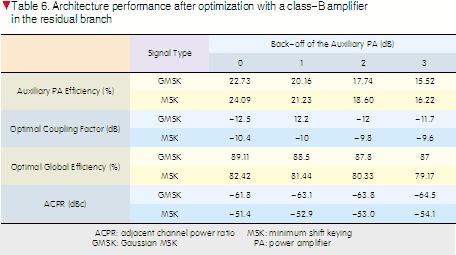
Given the excellent linearity of the class-AB amplifier, further efficiency within an acceptable margin of linearity can be achieved using a more efficient amplification class, such as class-B. Taking the same amplifier used in the single-ended case, we carried out the same simulations as in the previous study. With full power and three back-off levels (1 dB, 2 dB, and 3 dB), the power efficiency, optimal coupler, and linearity (expressed as ACPR) are as shown in Table 6. When power efficiency of the class-B amplifier is higher than that of the class-AB, optimal global efficiency is improved. Maximum power efficiency is around 89% for filtered GMSK and 82% for filtered MSK when the class-B amplifier is at full power. An average increase in power efficiency of 2.5% is then obtained compared to the same architecture with a class-AB amplifier. There is almost no impact on linearity. At worst, ACPR does not exceed -51 dBc, compared to -52 dBc with a class-AB amplifier. These excellent linearity levels can be explained as follows: The nonlinearity of the auxiliary amplifier affects only a small portion of the residual signal, which has a gain variation close to saturation. This distortion occurs at -γ dB (γ > 25 dB) below the main branch that carries the most important part of the information. Consequently, even when a class-B amplifier (more non-linear than class-AB) is used, linearity is maintained at a high level.
4.4 Considerations for Practical Implementation: Impact of Branch Imbalance on System Linearity
In this paragraph, we discuss the practical implementation issues that arise from non-ideal components in the proposed amplification architecture. In two-branch amplification systems, such as LINC and Feed-forward, non-ideal components cause imbalance between the two branches. This imbalance, in turn, leads to a non-ideal combination of both signal components and results in deteriorated linearity. Imbalances can be caused by transistor aging, temperature, dissimilarity in the up-conversion blocs, and combiner imperfections. To determine the impact of branch imbalance on linearity in the proposed architecture, we use the filtered MSK signal, which is more sensitive to non-linearities. The class-B amplifier without back-off is used in the second branch. We successively introduce phase imbalance, denoted by ΔΦ {0°, 2.5°, 5°}, and/or gain imbalance, denoted by ΔΦ {0 dB, 0.25 dB, 0.5 dB}, and calculate the ACPR for each scenario. A positive ΔΦ means that the phase of the main branch is larger than that of the second branch and vice versa. Similarly, positive ΔG means that the gain of the main branch is larger than that of the second branch and vice versa. For negative ΔG, the auxiliary class-B amplifier is used in a deeper compression, and lower overall linearity is expected. The results of these simulations are given in Table 7. An ideal case where ΔG = 0 and ΔΦ = 0 is the reference. The results show the impact of branch imbalance on system linearity. ACPR is degraded in all cases, and the threshold of -45 dBc is exceeded only when ΔG = -0.5 dB for all ΔΦ values (highlighted). The effect of phase variation is the same whether ΔΦ is positive or negative, whereas the positivity or negativity of ΔG directly impacts the amount of linearity degradation. This behavior is due to dissymmetry in gain between the branches. For positive ΔG, the signal of the main branch is uniformly amplified by that amount of gain. Uniform distortion is introduced into the system’s output signal, leading to low ACPR degradation. However, for negative ΔG, the auxiliary amplifier is excited at its compression region, and an increase in gain in the second branch amplifies both the linearly amplified portion of the residual signal (exciting the PA at its linear region) and the distorted portion of the residual signal (exciting the PA at its linear region) causing additional distortion. The resulting ACPR for that case is higher. The problem of branch imbalance is well known, and digital predistortion techniques [4], [5] can be used to correct it, as in LINC amplifiers [19], [20].

4.5 Comparison of Architectures
Here, we summarize the results obtained with the single ended class-B amplifier and the new two-branch technique. We previously supposed that the main amplifier was 100% efficient. However, in reality such efficiency cannot be achieved. To determine the efficiency of the proposed architecture with realistic amplifiers in the main branch, we evaluate the sensitivity of the system’s global efficiency to the efficiency of the main amplifier. We compute the global efficiency for different efficiencies of the main PA using a class-B auxiliary amplifier. In Fig. 8, we present these results and include the efficiency of the single-branch class-B. Compared t
[Abstract] This paper proposes a new two-branch amplification architecture that combines baseband signal decomposition with RF front-end optimization. In the proposed architecture, the filtered modulated signals are separated into two components that are then amplified independently and combined to regenerate an amplified version of the original signal. A branch with an efficient amplifier transmits a low-varying envelope signal that contains the main part of the information. Another branch amplifies the residual portion of the signal. The baseband decomposition and parameters of the RF part are optimized to find the configuration that gives the best power efficiency and linearity. For M-ary quadrature amplitude modulation (M-QAM) signals, this technique is limited in terms of power efficiency. However, for filtered continuous phase modulation (CPM) signals, especially for minimum shift keying (MSK) and Gaussian MSK (GMSK) signals, high power efficiency can be achieved with no significant impact on the overall linearity. The results show that this technique gives better performance than the single-ended class-B amplifier.
[Keywords] CPM modulation; M-QAM; RF power amplifiers; DC-RF efficiency; linearity; crest factor; shaping filters